At school we used a pair of equations to generate sinewaves.
  x = x + y / n
  y = y - x / n
Itterate them and apply y or x to a D to A converter. You get a sine wave as long at n is quite large.
One of the most striking things to me is the stability of the prediction.
The amplitude remains constant of very many cycles.
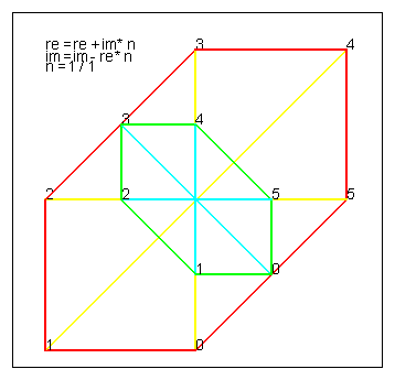
When you set n=1 the equations become:
Red starting with re=4,im=0
   re = re + im
   im = im - re
and
Green starting with re=2,im=0
   im = im - re
   re = re + im
The plots become this rather beautiful 'box kite'

Now the order of caluculation is shown to be important. We actually calculate
re( t+1 ) = re( t ) + im( t )
im( t+1 ) = im( t ) - re( t+1 )
This is a combination of the Forward Euler and Backward Euler integration.
Forward Euler uses the gradient at the start point, while Backward Euler uses the gradient at the back point.
Forward Euler over predicts and Backward Euler underpredicts the value of the next point.

I read in a book that many system of equations can be normalised to a set of first order differential equations.
These can be solved using matrix integration.
However, the step length of the integration must be less than the smallest time constant of any of the equations, otherwise the integration over predicts the next point beyond a value ever reached and the solution blows up.
You can see this in the diagram above. The Forward Euler predicts a value below the level that the red line is going to settle on. When you calculate the next gradient, it will predict violently up and the equations explode.
I always think of this when people propose rapid change at work and in the economy
below we calculate: The red ellipse is:
  re = re + im / 4
  im = im - re / 4
The green ellipse is:
  im = im - re / 4
  re = re + im / 4
As n is only 1/4 we expect some distortion.
Plotted re and im against itteration:

and plotted as Lissajous plots:

ref: http://www-gap.dcs.st-and.ac.uk/~history/Curves/Lissajous.html
These were generated using an AWK script.
This awk code uses the functions published at: http://www.doug.h.rice.btinternet.co.uk/awk_fns/index.htm and Delta Cad and Sun Open office.
The awk code produces:

 ####################################################
 #
 #	T.awk - A simple demo
 #
 ####################################################

 BEGIN {

 	FS	= ","
 	lastX 	= 0
 	lastY 	= 0

 	re 	= 4
 	im 	= 0
 	lastRe	= re
 	lastIm	= im
 	n	= 1 / 4

 	# Start the DXF file
 	F_header()

 	text( -4, 4.0, 0,  "re 	= re + im * n"  )
 	text( -4, 3.7, 0,  "im	= im - re * n"  )
 	text( -4, 3.4, 0,  "n = 1 / "  ( 1 / n ) )

         for ( x = 0 ; x < (3.14*2*1/n-1) ; x ++ ) {

 		im	= im - re * n
 		re 	= re + im * n


 		line( lastRe,lastIm,re,im,1)
 		line( 0,0,re,im,2)

 		text( re, im, 0,  " "+x)

 		line( x,lastRe-14,x+1,re-14,1)
 		line( x,lastIm-14,x+1,im-14,1)
 		line( x,-14,x+1,-14,0)
 		line( x,4-14,x,-4-14,0)
 		text( x, 0-14, 0,  " "+x)


 		lastRe	= re
 		lastIm	= im


 	}


 	re 	= 2
 	im 	= 0
 	lastRe	= re
 	lastIm	= im
 	#n	= 1 / 8


         for ( x = 0 ; x < (3.14*2*1/n-1) ; x ++ ) {

 		re 	= re + im * n
 		im	= im - re * n


 		line( lastRe,lastIm,re,im,3)
 		line( 0,0,re,im,4)

 		line( x,lastRe-14,x+1,re-14,3)
 		line( x,lastIm-14,x+1,im-14,3)


 		text( re, im, 0,  " "+x)

 		lastRe	= re
 		lastIm	= im


 	}


 }


 END {
 # draw Axis

 #	line( 0,0,100,0,0)  # black
 #	line( 0,1,100,1,1)  # red
 #	line( 0,2,100,2,2)  # yellow
 #	line( 0,3,100,3,3)  # green
 #	line( 0,4,100,4,4)  # cyan
 #	line( 0,5,100,5,5)  # blue
 #	line( 0,6,100,6,6)  # magenta
 #	line( 0,7,100,7,7)  # Black
 #	line( 0,8,100,8,8)  # black
 #	line( 0,9,100,9,9)  # black
 	# And finally tidy up the DXF file
 	F_end()

 }
When looking at the plots it is noticed that the lissajous figure is not circular, and that is you execute the equations in the order:
  re 	= re + im * n
  im	= im - re * n
you get the red ellipse.
If you execute the equations in the order:
  im	= im - re * n
  re 	= re + im * n
you get the green ellipse.
Is there any mileage in alternating the order of execution.
I tried this and the traces were more circular, but the frequency error was about the same.
The next stage is to plot the frequency error against quantization error.
I tried n/16 using 8 bit arithmatic and the frequency was high when n was 4.
I have also explored N= 1 and N= 0.5
When n=0.5 the cruves go unstable and blow up
When n=0.5002 you get a 'modulated sinewave'.
There is plenty to expriment with.
 INT_SERVICE_TMR2

 OStimeSlice

 	MOVFW	OSloops
 	MOVWF	OScnt

 OStimeSlice1
 	BCF		PIR1, TMR2IF

 	; want x=x+y/256
 	; want y=y-x/256

 	; x=x+y/256
 	BCF		STATUS,C
 	MOVFW	OSyh	;y/256
 	ADDWF	OSxl,f

 	; add the carry
 	BTFSC	STATUS,C
 	INCF	OSxh,f


 	; sign extend the MSB
 	; add 0xFF is MSB if OSyh is set
 	; note we add OSy
 	BTFSC	OSyh,7
 	DECF	OSxh,f


 	; y=y-x/256
 	BCF		STATUS,C
 	MOVFW	OSxh;x/256
 	SUBWF	OSyl,f    ;x/256

 	BTFSS	STATUS,C
 	DECF	OSyh,f

 	; now subtract sign extended OSx

 ;	MOVLW	0
 ;	BTFSC	OSxh,7
 ;	MOVLW	0xff
 ;	SUBWF	OSyh,f

 	; if MSB of OSxh,7 is set then sign extend and subtract -1 from OSyh by adding 1 to OSyh
 	BTFSC	OSxh,7
 	INCF	OSyh,f

 	DECFSZ	OScnt
 	GOTO	OStimeSlice1


 ; if you use OSyh at this point you get a discontinuty at the peaks
 ; if you use OSxh at this point you get a smaller discontinuty on the way up

 ;	MOVFW	OSyh	;y/256
 	MOVFW	OSxh	;y/256
 	ADDWF	OSoffset,w
 	BANKSEL	CCPR1L
 	MOVWF	CCPR1L

 	return
I set up the PWM using
 	ifdef buildPWM

 	; Configure Tmr 1
 	MOVLW	0x0 | 1<<TMR1ON | 3 <<T1CKPS0
 	MOVWF	T1CON

 	CLRF	OSxh
 	CLRF	OSxl
 	CLRF	OSyh
 	CLRF	OSyl

 	MOVLW	0x1f
 	MOVWF	OSxhStart
 	CLRF	OSxlStart
 	MOVLW	0x01
 	MOVWF	OSloops
 	MOVLW	0x40
 	MOVWF	OSoffset

 	endif
and
 PWinit	; set up the PWM
 	ifdef buildPWM

 	; Move the PWM period into PR2

 	MOVLW	0
 	CALL	EEread

 	BANKSEL	PR2
 	MOVWF	PR2

 	MOVLW	0
 	MOVWF	TRISB

 	MOVLW	1
 	CALL	EEread

 	BANKSEL	CCPR1L
 	MOVWF	CCPR1L

 	MOVLW	1 << TMR2ON
 	MOVWF	T2CON

 	BANKSEL	CCP1CON
 	MOVLW	1<< CCP1X | 1<< CCP1Y | ( .12 << CCP1M0	)
 	MOVWF	CCP1CON

 	;
 	; init SHM sinewave generator.
 	;

 	MOVFW	OSxhStart
 	MOVWF	OSxh

 	MOVFW	OSxlStart
 	MOVWF	OSxl

 	CLRF	OSyh
 	CLRF	OSyl

 	endif

 	RETURN
This was added to: /www/hp/freq/freq.htm
 	; x=x+y/16
 	BCF		STATUS,C
 	SWAPF	OSyh,w	;y/256
 	; sign extend OSyh
 	ANDLW	0x0F
 	BTFSC	OSyh,7
 	IORLW	0xF0

 	ADDWF	OSxh,f

 	; add the carry
 	BTFSC	STATUS,C
 	INCF	OSxh,f

 	; y=y-x/16
 	BCF		STATUS,C
 	SWAPF	OSxh,w	;y/256
 	; sign extend OSxh
 	ANDLW	0x0F
 	BTFSC	OSxh,7
 	IORLW	0xF0

 	SUBWF	OSyh,f    ;x/256

 	BTFSS	STATUS,C
 	DECF	OSyh,f

 	MOVFW	OSxh	;y/256
 	ADDWF	OSoffset,w
 	BANKSEL	CCPR1L
 	MOVWF	CCPR1L
 ;**************************************************************************
 ; SR002.ASM
 ;
 ; PROGRAM: Simple Serial Project
 ;
 ; DESCRIPTION:
 ;	simple serial project that receives serial commands
 ;   spaces are important
 ;
 ; Serial Commands:-
 ;
 ; File Regiters
 ;	<CR>wAADD;		write DD to register AA
 ;	<CR>rAA;  		read AA and output to serial port
 ;
 ; EEPROM
 ;	<CR>pAADD;		write DD to EEPROM register AA
 ;	<CR>gAA;  		read EEPROM register AA and output to serial port
 ;
 ; PRIPHERALS
 ;	<CR>f;			init PWM
 ;	; sets up PWM module
 ;	W92FF;	- PR2 	 - set PWM period max
 ;	W1532;	- CCPR1L	 - Duty Cycle / ON period
 ;	W8600;	- TRISB	 - All Outputs
 ;	W1204;	- T2CON	 - Set up Tmr 2
 ;	W173C;	- CCP1CON - Set up as PWM module.
 ;	W9265;	- PR2 	 - set PWM period for 10Khz if 4Mhz crystal.
 ;

 ;
 ; SERIAL PORT CONTROL:
 ;
 ;	PORT A0 is Serial input
 ;	PORT A0 is serial output
 ;
 ;	usb gmus-03 USB Serial Adapter
 ;
 ;	TX  D9 Pin 3 -[4k7]----+-----PA0
 ;	RX  D9 Pin 2 ----------/
 ;
 ;	GND D9 Pin 5 ---------------- 0V
 ;
 ; AUTHOR:  Douglas Rice
 ; Copyright 2004
 ;
 ;	Crystal:	4MHz
 ;
 ;	I/O used:-
 ;
 ;	; Port B is used for the LCD
 ;
 ;
 ;**************************************************************************


 ;--------------------------------------------------------------------------
 ; Sec 0.  #Defines tofor different chips
 ;--------------------------------------------------------------------------

 ; uncomment only one of these
 ;

 ;#define pic16F84 		1
 #define pic16F628 	1
 ;#define pic16F876 	1
 ;#define pic12F675 	1

     LIST    w=0, R=DEC

 ;--------------------------------------------------------------------------
 ; Sec 0.1 #Defines for 16F84
 ;--------------------------------------------------------------------------

 	ifdef pic16F84
     LIST    P=16F84, R=DEC
 	INCLUDE "p16F84.inc"

 	__idlocs  0x0084
 	__config  _XT_OSC & _PWRTE_ON & _WDT_OFF

 	cblock 	0x0c
 	endc


 PORT_RS232	  EQU  PORTA
 TRIS_RS232	  EQU  TRISA
 RS232tx         EQU  0	; Serial Out
 RS232rx         EQU  0	; Serial In needs to be equal to BUTTON_RS232


 	endif

 ;--------------------------------------------------------------------------
 ; Sec 0.2 #Defines for 16F628
 ;--------------------------------------------------------------------------

 	ifdef pic16F628
 #define 	buildPWM	1
     LIST    P=16F628, R=DEC
 	INCLUDE "p16F628.inc"

 	__idlocs  0x0628
 	__CONFIG _CP_OFF & _WDT_OFF & _BODEN_OFF & _PWRTE_ON & _INTRC_OSC_CLKOUT  & _MCLRE_OFF & _LVP_OFF

 	cblock 0x20
 	endc

 ; *********** I/O EQUATES **************

 PORT_RS232	  EQU  PORTA
 TRIS_RS232	  EQU  TRISA
 RS232tx         EQU  0	; Serial Out
 RS232rx         EQU  0	; Serial In needs to be equal to BUTTON_RS232


 	endif

 ;--------------------------------------------------------------------------
 ; Sec 0.3 #Defines for 16F876
 ;--------------------------------------------------------------------------

 	ifdef pic16F876
 #define 	buildPWM	1
     	LIST    P=16F876, R=DEC
 	INCLUDE "p16F876.inc"

 	__idlocs  0x0876
 	__CONFIG _CP_OFF & _DEBUG_OFF & _WRT_ENABLE_ON & _WDT_OFF & _BODEN_OFF & _PWRTE_ON  & _HS_OSC & _LVP_OFF

 	cblock 0x20
 	endc

 ; *********** I/O EQUATES **************

 PORT_RS232	  EQU  PORTA
 TRIS_RS232	  EQU  TRISA
 RS232tx         EQU  0	; Serial Out
 RS232rx         EQU  0	; Serial In needs to be equal to BUTTON_RS232


 	endif


 ;--------------------------------------------------------------------------
 ; Sec 0.4 #Defines for 12F675
 ;--------------------------------------------------------------------------

 	ifdef pic12F675
     	LIST    P=12F675, R=DEC

 	INCLUDE "p12F675.inc"
 	__idlocs  0x0675
 	__config  _PWRTE_ON & _WDT_OFF & _BODEN_OFF & _INTRC_OSC_NOCLKOUT & _MCLRE_OFF


 	cblock 0x20
 	endc

 ; *********** I/O EQUATES **************

 PORT_RS232  EQU  GPIO
 TRIS_RS232  EQU  TRISIO
 RS232tx     EQU  5	; Serial Out
 RS232rx     EQU  5	; Serial In needs to be equal to BUTTON_RS232

 PORTA		EQU  GPIO
 PORTB		EQU  GPIO

 TRISA		EQU  TRISIO
 TRISB		EQU  TRISIO
 	endif


 ;--------------------------------------------------------------------------
 ; Sec 1. Equates and Constants
 ;--------------------------------------------------------------------------
 ; The General Purpose Registers start at the end of the
 ; Special Purpose Registers.

 ; IPMentState values
 ; in normal running or in time setting modes
 ;

 ; DoTimeSlice bits
 ; these bits are set to schedule a timer chain event
 DTsS4event	EQU	0	;

 RUN_BUFF	EQU	0	;

 ; IPtrigMenu
 DTSFast			EQU	0

 ;--------------------------------------------------------------------------
 ; Sec 1.1 Button and LED
 ;--------------------------------------------------------------------------

 BUTTON_RS232	EQU	RS232rx	; EDG  - Bottom Buttom
 BUTTON_DOWN	EQU	6	; EDG  - Bottom Buttom

 ;--------------------------------------------------------------------------
 ; Sec 2.0 Variables
 ;--------------------------------------------------------------------------
 ; Variables start 0x0C
 ;

 ;	DoTimeSlice Bits, to schedule, set bit

 	cblock
 DoTimeSlice

 IPnew
 IPlast
 IPbuttonEvent

 IPnewFast
 IPlastFast
 IPbuttonEventUp

 IPtrigMenu

 ; variables used by Serial input and output routines
 RStxTemp
 RSloopCnt
 RSdelayCnt
 RSin
 RSout

 ; Serial input buffer
 RSipBuffCnt ; input buffer counter
 ; start of buffer
 RScmd
 RSAa		;
 RSaA		;
 RSDd		;
 RSdD		;
 RSterminator
 ; end of buffer

 ; temporary variables
 RSaddr
 RSdata
 ;


 ; Sinewave Oscillator variables

 OSxhStart
 OSxlStart
 OSloops
 OSoffset

 ; working variables
 OSxh
 OSxl
 OSyh
 OSyl
 OScnt

 	ENDC


 ;--------------------------------------------------------------------------
 ; Sec 3. MACROS
 ;--------------------------------------------------------------------------


 TEST_STRADDLE	MACRO	START
 	if high( $ ) != high( START )
 	    Error "Table straddles Page Boundary " + Start
 	endif
 	endm

 ;--------------------------------------------------------------------------
 ; Sec 4. Program Code
 ;--------------------------------------------------------------------------
 	ORG     0
 	GOTO    Start

 	ORG 	4
 	RETFIE
 	GOTO 	Intrtn

 ;--------------------------------------------------------------------------
 ; Sec 4.1	Main Program Init Code
 ;--------------------------------------------------------------------------

 Start

 	CALL 	INinit
 	CALL	INsayHello
 	GOTO	MainLoop


 INT_SERVICE_TMR2

 OStimeSlice

 	MOVFW	OSloops
 	MOVWF	OScnt

 OStimeSlice1
 	BCF		PIR1, TMR2IF

 	; want x=x+y/256
 	; want y=y-x/256

 	; x=x+y/256
 	BCF		STATUS,C
 	MOVFW	OSyh	;y/256
 	ADDWF	OSxl,f

 	; add the carry
 	BTFSC	STATUS,C
 	INCF	OSxh,f


 	; sign extend the MSB
 	; add 0xFF is MSB if OSyh is set
 	; note we add OSy
 	BTFSC	OSyh,7
 	DECF	OSxh,f


 	; y=y-x/256
 	BCF		STATUS,C
 	MOVFW	OSxh;x/256
 	SUBWF	OSyl,f    ;x/256

 	BTFSS	STATUS,C
 	DECF	OSyh,f

 	; now subtract sign extended OSx

 ;	MOVLW	0
 ;	BTFSC	OSxh,7
 ;	MOVLW	0xff
 ;	SUBWF	OSyh,f

 	; if MSB of OSxh,7 is set then sign extend and subtract -1 from OSyh by adding 1 to OSyh
 	BTFSC	OSxh,7
 	INCF	OSyh,f

 	DECFSZ	OScnt
 	GOTO	OStimeSlice1


 ; if you use OSyh at this point you get a discontinuty at the peaks
 ; if you use OSxh at this point you get a smaller discontinuty on the way up

 ;	MOVFW	OSyh	;y/256
 	MOVFW	OSxh	;y/256
 	ADDWF	OSoffset,w
 	BANKSEL	CCPR1L
 	MOVWF	CCPR1L

 	return


 ;--------------------------------------------------------------------------
 ; Sec 4.2	Main Program
 ;--------------------------------------------------------------------------

 MainLoop
 		BTFSC	PIR1, TMR2IF
 		CALL	INT_SERVICE_TMR2


 		CALL	IPtimesliceFast

 		; test for rising edge
 		BTFSC	IPbuttonEventUp,BUTTON_RS232	; RS232 input start
 		CALL	IPrs232

 		MOVF	DoTimeSlice,w
 		Bz		MainLoop

 		BTFSC	DoTimeSlice,RUN_BUFF
 		CALL	DLrunBuff


 		GOTO 	MainLoop


 ;--------------------------------------------------------------------------
 ; Sec 5.	Subroutines, procedures and functions
 ;--------------------------------------------------------------------------


 ;--------------------------------------------------------------------------
 ; Sec 5.1	Button Poll Routine
 ;--------------------------------------------------------------------------

 IPtimeslice
 		;	--_____	button press
 		;	----___

 		;	__-----  /IPnew
 		;	----___  IPlast
 		;	__--___
 		;
 		;
 		;
 		; This reads all Port A inputs and looks for Press
 		MOVFW	IPnew
 		MOVWF	IPlast
 		MOVFW	PORTA
 		MOVWF	IPnew
 		; IP last contains new setting, IPlast contains previous
 		; look for falling edges
 		COMF	IPnew,W
 		ANDWF	IPlast,W
 		; now force IPbuttonEvent bits to high for new pressed button
 		; the service routine should reset the bit to clear the event.
 		IORWF	IPbuttonEvent,F
 		RETURN

 IPtimesliceFast
 		; Look for rising edges
 		MOVFW	IPnewFast
 		MOVWF	IPlastFast
 		MOVFW	PORT_RS232
 		MOVWF	IPnewFast

 		COMF	IPlastFast,W
 		ANDWF	IPnewFast,W
 		IORWF	IPbuttonEventUp,F
 		RETURN
 ;--------------------------------------------------------------------------
 ; Sec 5.2
 ;--------------------------------------------------------------------------

 ;--------------------------------------------------------------------------
 ; Sec 5.2	.1 run process on request
 ;--------------------------------------------------------------------------

 DLrunBuff
 	BCF	DoTimeSlice,RUN_BUFF
 ;	MOVFW	'#'
 ;	CALL 	RStxChar


 	MOVFW	RSin
 	CALL	RSbuffInput
 	return


 ;--------------------------------------------------------------------------
 ; Sec 5.3	 Button Input functions
 ;--------------------------------------------------------------------------


 IPdownPressed
 	BCF IPbuttonEvent,BUTTON_DOWN
 	return


 IPrs232
 	BCF IPbuttonEventUp,BUTTON_RS232
 	GOTO RSrs232in


 ;--------------------------------------------------------------------------
 ; Sec 5.4	 Clock Chain Routine
 ;--------------------------------------------------------------------------

 CLtimeslice
 		;
 		BTFSS	INTCON,T0IF
 		RETURN

 		; TMR0 timeout
 		BCF		INTCON,T0IF
 		BSF		DoTimeSlice,DTsS4event

 		CALL	IPtimeslice
 		RETURN


 ;--------------------------------------------------------------------------
 ; Sec 5.5 	Serial Input Routine
 ;--------------------------------------------------------------------------

 ;**************************************************
 RSrs232in

 ; Test is in main loop or uncomment code below to
 ; spin for a start bit
 ;		CLRWDT
 ;		BTFSS	PORT_RS232,RS232rx
 ;		GOTO	RSrs232in


 		CALL	RSdelayBit			; delay through Stop Bit
 		CALL 	RSdelayHalfBit		; delay halfway into first bit

 		movlw	8
 		movwf	RSloopCnt
 RSrs232inL0
 		MOVFW	PORT_RS232
 		ANDLW	 1<< RS232rx		; mask off bit
 		ADDLW	-1<< RS232rx		; use ripple carry to move into C
 		RRF		RSin,F

 		CALL	RSdelayBit
 		DECFSZ	RSloopCnt,f
 		goto	RSrs232inL0

 		; test for Stop bit
 		COMF	RSin,f
 		BSF		DoTimeSlice,RUN_BUFF
 		RETURN


 ;--------------------------------------------------------------------------
 ; Sec 5.6 	Serial Output Routines
 ;--------------------------------------------------------------------------


 RSwrtHexNibble	; currently only displays 0..9, A..F
 	ANDLW	0x0F
 	ADDLW	0x06	; is it A..F, if so trigger a digit overflow
 	SKPNDC
 	ADDLW	7; subtract 10, then add 'A'-'0'
 	ADDLW	0x30-6	; Subtract extra 6 added to cause DC
 	MOVWF	RSout
 	GOTO	RStxChar

 RStxChar
 	;
 	; Output Start Bit
 	; Start bit is low, data bits are inverted
 	;

 	movwf	RStxTemp
 	comf	RStxTemp,f
 	BCF		PORT_RS232,RS232tx

 	; Make RS232 pin an ouput while transmitting character
 	BANKSEL  TRIS_RS232
 	BCF		TRIS_RS232,RS232tx
 	BANKSEL  PORT_RS232

 	; 1200 baud output
 	; move the char into RStxtemp, it is destroyed.
 	;Start Bit
 	BSF		PORT_RS232,RS232tx

 	call	RSdelayBit
 	movlw	8
 	movwf	RSloopCnt

 RStxCharLp1

 	; After start bit, which is 1, then test each bit
 	; I need to set PA:0 to same as LSB RStxTemp
 	; this compares PA:0 with RStxTemp so see if it needs toggling
 	; The xorwf PORT_RS232,f causes the bit to be toggled if required.

 	RRF		RStxTemp,f
 	movfw	STATUS
 	andlw	1 << C			; mask off bit
 	addlw   ( 1 << RS232tx) -1	; shift bit by using a ripple carry
 	xorwf	PORT_RS232,W			; Doeas output need toggling ?
 	andlw	1 << RS232tx		; Mask off output pin
 	xorwf	PORT_RS232,f			; Toggle output pin if needed
 	call	RSdelayBit			; delay bit


 	decfsz	RSloopCnt,f
 	goto	RStxCharLp1

 	BCF		PORT_RS232,RS232tx
 	call	RSdelayBit	; apply stop bit

 	; Make RS232 pin an input so that main loop can test for start bit
 	BANKSEL  TRIS_RS232
 	BSF		TRIS_RS232,RS232tx
 	BANKSEL  PORT_RS232

 	RETURN


 ; timing functions to delay serial routines for a bit or half bit.

 RSdelayHalfBit
 		MOVLW	0x1D		; shorten delay as edge detector takes about 22 us for 4800 baud
 		GOTO	RSdelayBit0

 RSdelayBit
 		NOP
 		MOVLW	0x40	 ; for 4800 baud

 RSdelayBit0
 		MOVWF	RSdelayCnt
 RSdelayBit1	DECFSZ	RSdelayCnt,f		; 1
 		GOTO	RSdelayBit1		; 2 clk
 		CLRWDT
 		RETURN


 ;--------------------------------------------------------------------------
 ; Sec 5.7 	Serial Output Format Routines
 ;--------------------------------------------------------------------------

 RSasciiToNibble
 	MOVWF	RSin
 	; if 0..1 then 0x30 to 0x39
 	; if A..F then 0x41 to 0x46
 	; if a..f then 0x61 to 0x66
 	; test if bit 4 set and assume a letter or number
 	BTFSS	RSin,4
 	ADDLW	0x09		; letter so add 9
 	ANDLW	0x0F		; mask of nibble
 	return


 ;--------------------------------------------------------------------------
 ; Sec 5.8 	Serial Input Buffer Routine
 ;--------------------------------------------------------------------------

 ; take serial input CAADD and put into buffer
 ; if char id ; the do command
 ; if char is CR reset buffer pointer
 ; if buff end then reset buff pointer


 RSipbuffStart	EQU RScmd
 RSipbuffEnd	EQU RSterminator

 RSbuffInput
 	MOVWF	RSin
 	; look for line feed and reset buff cnt
 	ADDLW	-0x0D
 	BNZ		RSbuffInput1
 	MOVLW	RSipbuffStart
 	MOVWF	RSipBuffCnt
 	RETURN

 RSbuffInput1
 	; end of line command - do command
 	ADDLW	-';'+0x0D
 	BNZ		RSbuffInput2
 	GOTO	RSbuffInputProcess

 RSbuffInput2
 	; Store the current time into the next register.
 	MOVFW	RSipBuffCnt
 	MOVWF	FSR
 	MOVFW	RSin
 	MOVWF	INDF
 	INCFSZ	RSipBuffCnt,f
 	MOVFW	RSipBuffCnt

 	ADDLW	-(RSipbuffEnd+1)
 	; Check if the end of memory
 	SKPZ
 	GOTO	RSbuffInputEnd1
 	MOVLW	RSipbuffStart
 	MOVWF	RSipBuffCnt

 	; reset cursor
 	MOVLW	0x0D
 	CALL 	RStxChar
 	RETURN


 RSbuffInputProcess
 	MOVLW	RSipbuffStart
 	MOVWF	RSipBuffCnt

 	MOVFW	RSAa
 	; if 0..1 then 0x30 to 0x39
 	; if A..F then 0x41 to 0x46
 	; if a..f then 0x61 to 0x66
 	; test if bit 4 set and assume a letter or number

 	BTFSS	RSAa,4
 	ADDLW	0x09		; letter so add 9
 	ANDLW	0x0F		; mask of nibble
 	MOVWF	RSin
 	SWAPF	RSin,F

 	MOVFW	RSaA
 	BTFSS	RSaA,4
 	ADDLW	0x09		; letter so add 9
 	ANDLW	0x0F		; mask of nibble
 	ADDWF	RSin,w
 	MOVWF	RSaddr

 	MOVFW	RSDd
 	BTFSS	RSDd,4
 	ADDLW	0x09		; letter so add 9
 	ANDLW	0x0F		; mask of nibble
 	MOVWF	RSin
 	SWAPF	RSin,F

 	MOVFW	RSdD
 	BTFSS	RSdD,4
 	ADDLW	0x09		; letter so add 9
 	ANDLW	0x0F		; mask of nibble
 	ADDWF	RSin,w
 	MOVWF	RSdata

 	; CALL 	RStxChar

 	; got to end of buffer so process. does not allow for backspace

 	; Write to file register
 	MOVLW	-'w'
 	ADDWF	RScmd,w	; test to see if command is s, if so save into register.
 	bnz  	RSbuffInput3

 	MOVFW	RSaddr
 	MOVWF	FSR

 	MOVFW	RSdata
 	MOVWF	INDF


 	MOVLW	'*'
 	CALL 	RStxChar
 	GOTO	RSbuffInputEnd


 RSbuffInput3

 	; put octet in EEPROM
 	MOVLW	-'p'
 	ADDWF	RScmd,w	; test to see if command is s, if so save into register.
 	bnz  	RSbuffInput4

 	MOVFW	RSaddr
 	CALL	EEsetAddr

 	BANKSEL	RSdata
 	MOVFW	RSdata
 	CALL	EEwrt

 	MOVFW	RSdata
 	MOVWF	INDF

 	MOVLW	'*'
 	CALL 	RStxChar

 	GOTO	RSbuffInputEnd


 RSbuffInput4
 	; read from file register
 	MOVLW	-'r'
 	ADDWF	RScmd,w	; test to see if command is s, if so save into register.
 	bnz  	RSbuffInput5

 	MOVFW	RSaddr
 	MOVWF	FSR

 	MOVFW	INDF
 	MOVWF	RSin

 RSbuffInput4display
 	MOVLW	'='
 	CALL 	RStxChar

 	SWAPF	RSin,w
 	CALL	RSwrtHexNibble

 	MOVFW	RSin
 	CALL	RSwrtHexNibble

 	GOTO	RSbuffInputEnd


 RSbuffInput5
 	; get from EEPROM register
 	MOVLW	-'g'
 	ADDWF	RScmd,w	; test to see if command is s, if so save into register.
 	bnz  	RSbuffInput6

 	MOVFW	RSaddr
 	CALL	EEread
 	MOVWF	RSin

 	GOTO	RSbuffInput4display


 RSbuffInput6
 	; Initilize PWM
 	MOVLW	-'f'
 	ADDWF	RScmd,w	; test to see if command is s, if so save into register.
 	bnz  	RSbuffInput7
 	CALL	PWinit;
 	MOVLW	'*'
 	CALL 	RStxChar
 	GOTO	RSbuffInputEnd

 RSbuffInput7

 RSbuffInputEnd

 	MOVLW	0x0D
 	CALL 	RStxChar

 	MOVLW	0x0A
 	CALL 	RStxChar

 RSbuffInputEnd1

     return

 ;--------------------------------------------------------------------------
 ; Sec 5.9 Initilization code -
 ;--------------------------------------------------------------------------


 INinit
 	; Enable Interupts
 	MOVLW	H'00'
 	MOVWF	INTCON

 	CLRF PORT_RS232 ;Initialize PORT_RS232 by setting
 	;output data latches

 	ifdef pic12F675
 	; get the Oscillator calibration

 	;MOVLW	0x6C		; load the Calib
 	BSF		STATUS,RP0
 	CALL 	OscCalValue
 	MOVWF	OSCCAL

 	BANKSEL 	CMCON
 	MOVLW 	0X07 ;Turn comparators off and
 	MOVWF 	CMCON ;enable pins for I/O

 	BANKSEL 	ANSEL
 	CLRF	ANSEL

 	endif


 	ifdef pic16F628
 	BANKSEL CMCON
 	MOVLW 0X07 ;Turn comparators off and
 	MOVWF CMCON ;enable pins for I/O

 	endif

 	ifdef pic16F876
      ;make AtoD inputs digital
 	BANKSEL ADCON1
 	MOVLW 0X07 ;Turn comparators off and
 	MOVWF ADCON1 ;enable pins for I/O
 	endif


 	banksel	TRISB
 	MOVLW	0XF0
 	MOVWF	TRISB
 	BSF		TRIS_RS232, RS232tx 	; Make PORT_RS232 3:0 INPUTS.


 	banksel	RSipbuffStart
 	; reset input buffer
 	MOVLW	RSipbuffStart
 	MOVWF	RSipBuffCnt

 	; Change Prescaler
 	CLRWDT

 	; Configure Tmr 0
 	BSF		STATUS,RP0
 	; Set up prescaller for 8192 / 16 = 512 ticks perseconds.

 	MOVLW	0x0 + 2 	; For Tmr0 0=/2, 1=/4, 2=/8,3=/16
 	MOVWF	OPTION_REG
 	BCF		STATUS,RP0

 	ifdef buildPWM

 	; Configure Tmr 1
 	MOVLW	0x0 | 1<<TMR1ON | 3 <<T1CKPS0
 	MOVWF	T1CON

 	CLRF	OSxh
 	CLRF	OSxl
 	CLRF	OSyh
 	CLRF	OSyl

 	MOVLW	0x1f
 	MOVWF	OSxhStart
 	CLRF	OSxlStart
 	MOVLW	0x01
 	MOVWF	OSloops
 	MOVLW	0x40
 	MOVWF	OSoffset

 	endif

 	CLRF	DoTimeSlice
 	CLRF	IPbuttonEvent
 	CLRF	IPbuttonEventUp


 	return

 INsayHello
 	; print out power on message
 	MOVLW	0x0D
 	CALL 	RStxChar

 	MOVLW	0x0A
 	CALL 	RStxChar

 	MOVLW	'S'
 	CALL 	RStxChar

 	MOVLW	'R'
 	CALL 	RStxChar

 	MOVLW	0x0D
 	CALL 	RStxChar

 	MOVLW	0x0A
 	CALL 	RStxChar
 	return


 ;--------------------------------------------------------------------------
 ; Sec 5.10 	EEprom Routines for 16F628
 ;--------------------------------------------------------------------------

 EEread
 		; w contains address
 		banksel	EEADR
 		MOVWF	EEADR
 		BSF		EECON1,RD
 		MOVFW	EEDATA
 		banksel	0
 		RETURN

 EEsetAddr
 		banksel	EEADR
 		MOVWF	EEADR
 		RETURN

 EEwrt		; blocking, EEADR and EEDATA set up.
 		;		BSF	STATUS,RP0
 		banksel 	EEDATA
 		MOVWF	EEDATA
 		BCF		INTCON,GIE
 		BCF		EECON1,EEIF
 		BSF		EECON1,WREN
 		MOVLW	0x55
 		MOVWF	EECON2
 		MOVLW	0xAA
 		MOVWF	EECON2
 		BSF		EECON1,WR
 		; Now wait for EEwrt to finish write
 EEwaitForWrt	; block until EEPROM write has finished.
 		BCF		EECON1,WREN	; disable EROM
 		BTFSC	EECON1,WR
 		GOTO	EEwaitForWrt
 		BCF		EECON1,EEIF	; EEPROM finished
 		; BCF	STATUS,RP0

 		banksel	0
 		RETURN

 ;--------------------------------------------------------------------------
 ; Sec 5.11	Routines to set up PWM on 16F628
 ;--------------------------------------------------------------------------


 PWinit	; set up the PWM
 	ifdef buildPWM

 	; Move the PWM period into PR2

 	MOVLW	0
 	CALL	EEread

 	BANKSEL	PR2
 	MOVWF	PR2

 	MOVLW	0
 	MOVWF	TRISB

 	MOVLW	1
 	CALL	EEread

 	BANKSEL	CCPR1L
 	MOVWF	CCPR1L

 	MOVLW	1 << TMR2ON
 	MOVWF	T2CON

 	BANKSEL	CCP1CON
 	MOVLW	1<< CCP1X | 1<< CCP1Y | ( .12 << CCP1M0	)
 	MOVWF	CCP1CON

 	;
 	; init SHM sinewave generator.
 	;

 	MOVFW	OSxhStart
 	MOVWF	OSxh

 	MOVFW	OSxlStart
 	MOVWF	OSxl

 	CLRF	OSyh
 	CLRF	OSyl

 	endif

 	RETURN


 ;--------------------------------------------------------------------------
 ; Sec 6.0		Interrupt Routines
 ;--------------------------------------------------------------------------

 Intrtn
 		RETFIE

 ;--------------------------------------------------------------------------
 ; Program End
 ;--------------------------------------------------------------------------
 	ifdef pic12F675

 	org	0x3FD
 	RETLW	0x6C
 	RETLW	0x6C
 OscCalValue
 	RETLW	0x6C
 	endif
 LastProgWord

 ;--------------------------------------------------------------------------
 ; Sec 7.0		EEPROM data
 ;--------------------------------------------------------------------------
 		ORG	0x2100
 		; first 2 on and off are general ones
 		DE	.100,.50  ; 4

 	cblock
 LastVar
 	endc
                END