
 RC servos are controlled by a signal that goes high for
between 1ms to 2ms.
RC servos are controlled by a signal that goes high for
between 1ms to 2ms.
This pulse is repeated every 10 to 20ms, but it's timing does not control the position of the servo.
My servo seems to hit the endstops with timings of less than 0.63ms and greater than 1.42ms.
I brought a servo, and this code is a demo to get it to work.
Originally, the idea was a program to output a different width
pulse on each port B output and it still does.
Connect the control wire from the servo, to a different pin on port B, and
the servo should move to a new position.
This code is module T2.
It starts by setting all the bits in Port B and Port A. It then
runs through a set of inline delays, and each time, it resets a
bit.
This works, and the servo position remains stable.
Connect Port A3 to the servo's control signal, and the pulse
width can be increased and decreased by pressing buttons pulling
PB6 and PB7 low.
Press both buttons and the servo is set to a nominal midpoint.
The counts limits at the max and does not wrap round.
The code is for the 16F628. The 16F628, has an internal 4Mhz Oscillator, and I have disabled the MCLR pin, so no pull up resitor is required. Do not forget to connect 0V to pin 5, and 5V to Pin 14, and 5 volts to the Servo
PICS do not like voltages above 5.5 volts, so decouple the Supply to the PIC from the Servo supply.
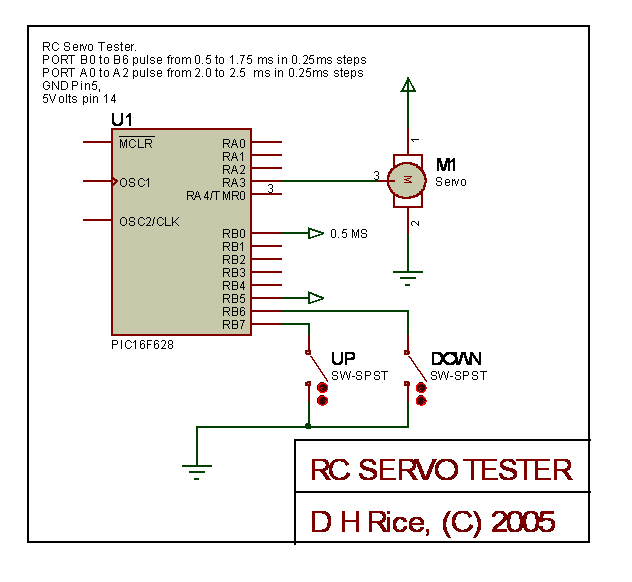

This code is written for the PIC16F628, as it has an internal RC 4M Hz clock.
Your only need a Pic16F628, two buttons, the servo, and the 5 volts power source.The compiled code is code . Here is a web site that has some more information about servos and another tester.
 ;**********************************************************************
 ;   SV011.asm - servo tester
 ;
 ;   PB0 - PB5 and PA0 to PA3 fixed pulse widths
 ;
 ;	Servos need a 1.5ms pulse every 20ms
 ;
 ;	Vary the width of the 1.5ms pulse to change the position.
 ;
 ;	If the pulses are too close together, then the servo can get confused
 ;	If the pulses are too far apart, the servo may be rough.
 ;
 ;
 ;   The code here outputs to port B 1ms to 2ms at 125us intervals
 ;
 ;   Port A3 provides a pulse from 1ms to 2ms controlled by PB6 and PB7
 ;
 ;   These pulses shoule be repeated about every 20ms
 ;
 ;   If you make PB6 or PB7 low PA3's pulse width changes:
 ;	PB6 Clockwise
 ;	PB7 Anticlockwise
 ;	PB6 and PB7 center
 ;
 ;
 ;**********************************************************************
 ;
 ;    Filename:	  SV011.asm
 ;    Date:          26th September 2005
 ;    File Version:  Draft 1C
 ;
 ;    Author:        Doug Rice
 ;    Company:       DougTronics
 ;
 ;
 ;**********************************************************************
 ;
 ;    Files required:                                                  *
 ;
 ;
 ;
 ;**********************************************************************
 ;
 ;    Notes:
 ;
 ;
 ;
 ;
 ;**********************************************************************


 	list      p=16f628            ; list directive to define processor
 	#include <p16f628.inc>        ; processor specific variable definitions

 	__CONFIG _CP_OFF & _WDT_OFF & _BODEN_OFF & _PWRTE_ON & _INTRC_OSC_CLKOUT  & _MCLRE_OFF & _LVP_OFF

 ;	__CONFIG _CP_OFF & _WDT_OFF & _BODEN_OFF & _PWRTE_ON & _ER_OSC_CLKOUT  & _MCLRE_OFF & _LVP_OFF

 ;	__CONFIG 0x3FFF

 ; '__CONFIG' directive is used to embed configuration data within .asm file.
 ; The lables following the directive are located in the respective .inc file.
 ; See respective data sheet for additional information on configuration word.


 ;***** VARIABLE DEFINITIONS
 w_temp        EQU     0x70        ; variable used for context saving
 status_temp   EQU     0x71        ; variable used for context saving

 BUTTON_UP	EQU 7
 BUTTON_DOWN	EQU 6
 BUTTON_BOTH	EQU 6

 	cblock	0x20	; 16F628

 	  ; delay variables
 	  DLdelcnt
 	  DLdelcnt1

 	  ; position memories
 	  T3pos
 	  T3poscnt

 	  ; Input variables
 	  IPnew
 	  IPlast
 	  IPbuttonEvent
 	  IPbuttonEvent2

 	endc

 ;**********************************************************************
 		ORG     0x000             ; processor reset vector
 		goto    main              ; go to beginning of program


 		ORG     0x004             ; interrupt vector location
 		movwf   w_temp            ; save off current W register contents
 		movf	STATUS,w          ; move status register into W register
 		movwf	status_temp       ; save off contents of STATUS register

 ; isr code can go here or be located as a call subroutine elsewhere

 		movf    status_temp,w     ; retrieve copy of STATUS register
 		movwf	STATUS            ; restore pre-isr STATUS register contents
 		swapf   w_temp,f
 		swapf   w_temp,w          ; restore pre-isr W register contents
 		retfie                    ; return from interrupt


 main
 	; Servo Loop.
 	; PORT B bits have one of 8 settings
 	; The pulse widths on PORT B vary from 1ms to 2ms in 125us steps.
 	; this seems to work.

 	CLRF PORTA ;Initialize PORTA by setting
 	;output data latches
 	BANKSEL CMCON
 	MOVLW 0X07 ;Turn comparators off and
 	MOVWF CMCON ;enable pins for I/O


 	BANKSEL OPTION_REG
 	BCF	OPTION_REG,NOT_RBPU

 	BANKSEL TRISB
 	CLRF	TRISB
 	MOVLW	0x00
 	MOVWF	TRISA

 	MOVLW	0xC0
 	MOVWF	TRISB

         BANKSEL PORTB
 	CLRF	PORTA
 	CLRF	PORTB


 	; set up initial position to mid point
 	CLRF	T3pos
 	MOVLW	0x07
 	MOVWF	T3pos


 mainLoop
 	CALL T2

 	CALL T3

 	; http://www.rc-cam.com/servotst.htm says that the frame rate should be about 20ms
 	; If it is too short the servo may be jerky.
 	; padd out the fram a bit
 	CALL	DLdelay2ms
 	CALL	DLdelay2ms

 	call	IPtimeslice

 	CALL	DLdelay2ms
 	CALL	DLdelay2ms
 	CALL	DLdelay2ms


 	BTFSS	IPbuttonEvent,BUTTON_UP	; On BUTTON_SET Press
 	CALL	IPupPressed

 	BTFSS	IPbuttonEvent,BUTTON_DOWN	; On BUTTON_NEXT Press
 	CALL	IPdownPressed

 	BTFSS	IPbuttonEvent2,BUTTON_BOTH	; On BUTTON_BOTH Press
 	CALL	IPbothPressed


 	GOTO	mainLoop


 T2
 	;
 	; Apply a different width pulse on each PIN
 	; connect Servo control to a pin to set position.
 	;
 T2loop

 	;portB0=500us
 	;portB1=625us
 	;portB2=750us
 	;portB3=875us
 	;portB4=1000us
 	;portB5=1125us
 	;portA0=1250us
 	;portA1=1500us
 	;portA2=1750us

 	;portB6 - input step up
 	;portB7 - input step down


 	MOVLW	0xFF
 	MOVWF	PORTB
 	MOVLW	0x07
 	MOVWF	PORTA

 	call DLdelay500us

 	MOVLW	0xFE
 	MOVWF	PORTB
 	call DLdelay125us

 	MOVLW	0xFC
 	MOVWF	PORTB
 	call DLdelay125us

 	MOVLW	0xF8
 	MOVWF	PORTB
 	call DLdelay125us

 	MOVLW	0xF0
 	MOVWF	PORTB
 	call DLdelay125us

 	MOVLW	0xE0
 	MOVWF	PORTB
 	call DLdelay125us

 	MOVLW	0xC0
 	MOVWF	PORTB
 	call DLdelay125us

 	MOVLW	0x06
 	MOVWF	PORTA
 	call DLdelay125us

 	MOVLW	0x04
 	MOVWF	PORTA
 	call DLdelay125us

 	MOVLW	0x00
 	MOVWF	PORTA

 	call DLdelay2ms
 	call DLdelay2ms
 	call DLdelay2ms

 	return


 T3
 	;
 	; Apply a pulse width of 500us+ ( T3pos*125us ) on PA3
 	; connect Servo control to a pin to set position.
 	;
 	;

 	MOVFW	T3pos
 	MOVWF	T3poscnt
 	INCF	T3poscnt,F
 	BSF	PORTA,3
 	call DLdelay500us
 T3loop10
 	DECFSZ	T3poscnt,f
 	GOTO	T3loop11
 	goto	T3loop12
 T3loop11
 	call DLdelay125us
 	goto	T3loop10
 T3loop12
 	BCF	PORTA,3
 	return


 IPupPressed
 	BSF	IPbuttonEvent,BUTTON_UP
 	INCF	T3pos,w
 	ANDLW	0x0F
 	; limit and prevent wrap around
 	SKPNZ
 	MOVLW	0x0F
 	MOVWF	T3pos

 	return

 IPdownPressed
 	BSF	IPbuttonEvent,BUTTON_DOWN
 	DECF	T3pos,w
 	ANDLW	0x0F
 	; limit and prevent wrap around
 	SKPNZ
 	MOVLW	0x01
 	MOVWF	T3pos
 	return

 IPbothPressed
 	; center the servo
 	BSF	IPbuttonEvent2,BUTTON_BOTH
 	MOVLW	0x07
 	MOVWF	T3pos
 	return


 DLdelay100us
 	movlw	0x0D
 	goto 	DLdelayShort

 DLdelay125us
 	movlw	0x11
 	goto 	DLdelayShort

 DLdelay500us
 	movlw	0x46
 	goto 	DLdelayShort

 DLdelay1ms
 	movlw	0x80
 ;;	movlw	0x90 ; this is 1ms
 	goto 	DLdelayShort

 DLdelay2ms
 	movlw	0xFF ; longest
 	goto 	DLdelayShort


 DLdelayShort
 	movwf	DLdelcnt
 DLdelayShort1
 	GOTO $+1
 	GOTO $+1
 	DECFSZ	DLdelcnt,f
 	goto	DLdelayShort1
 	return


 IPtimeslice
 		;	----___
 		;	--_____
 		;
 		;	Single button event of falling edge, ie when button pressed
                 ;       both button events when both buttons are found to be low

 		; This reads all Port B inputs and looks for Press
 		MOVFW	IPnew
 		MOVWF	IPlast
 		MOVFW	PORTB
 		MOVWF	IPnew
 		; IP last contains new setting, IPlast contains previous
 		COMF	IPlast,W
 		IORWF	IPnew,W
 		; now force IPbuttonEvent bits to low for new pressed button
 		; the service routine should set the bit to clear the event.
 		ANDWF	IPbuttonEvent,F


 		; if both buttons are low on both scans then bit will be low
 		MOVFW	IPnew
 		IORWF	IPlast,w

 		; now mask  off bits of interest
 		ANDLW	1<<BUTTON_UP | 1 << BUTTON_DOWN

 		SKPZ
 		RETURN
 		BCF	IPbuttonEvent2,BUTTON_BOTH
 		; if both buttons low it's a BUTTON_BOTH event,
 		; so cancel any BUTTON_UP and BUTTON_DOWN events.
 		MOVLW	1<<BUTTON_UP | 1 << BUTTON_DOWN
 		IORWF	IPbuttonEvent,F

 		RETURN

 		END                       ; directive 'end of program'